System Mounting Installations
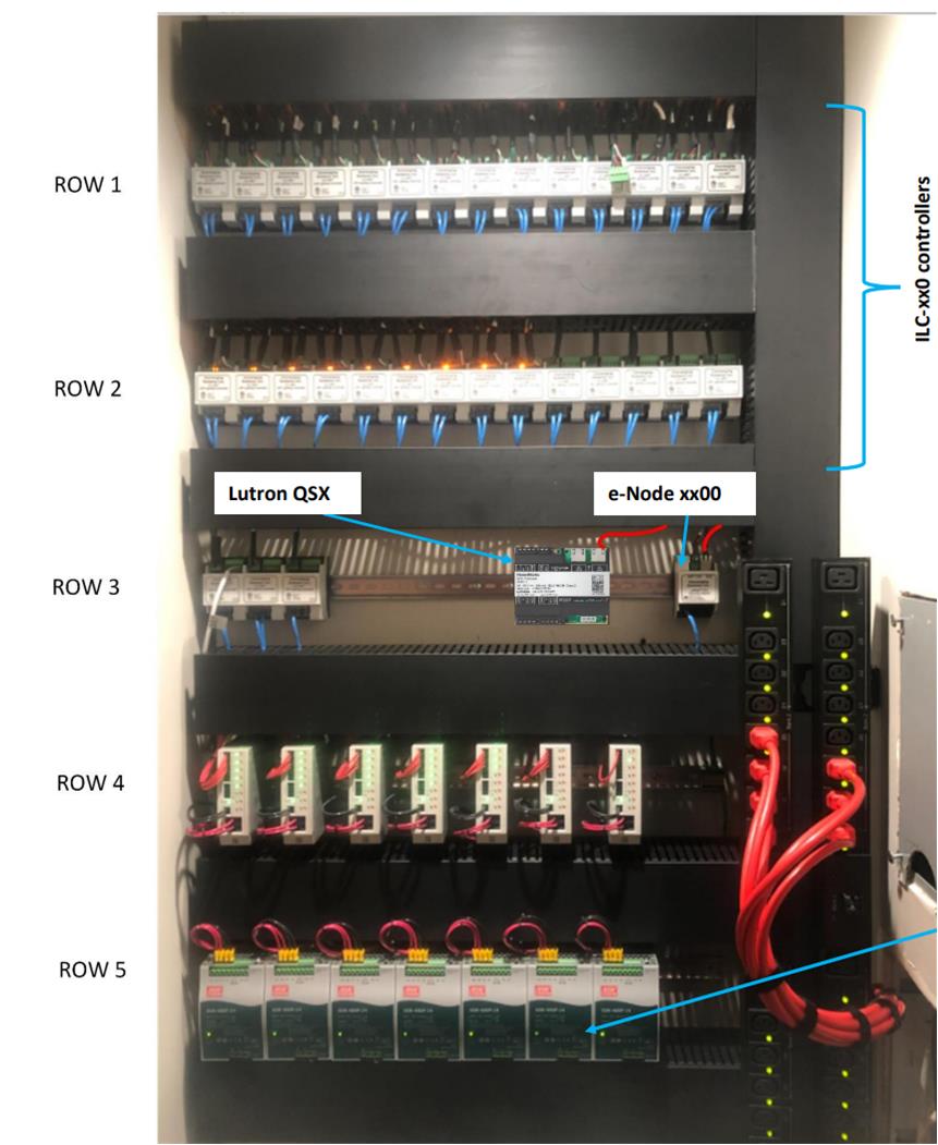
This section details presents some well-planned DIN-RAIL installations that combine Class 1 and Class 2 wiring including a Converging Systems' e-Node and ILC-xxx devices, a Lutron Homeworks QSX processor and peripheral equipment.

Components
| Row # | Component | Function |
|---|---|---|
| DIN Rail Box itself | Future Automation DIN-Rail Enclosure | Approved mounting system for DIN-RAIL equipment |
| Row 1 | ILC-4x0 controllers | Controller for Constant Voltage LED linears |
| Row 2 | ILC-4x0 controllers | Controller for Constant Current LED linears |
| Row 3 | Hybrid: ILC-xxx controllers/Lutron Controller/e-Node | (left three components same as above) +Lutron QSX + CSI e-Node for control of system |
| Row 4 | Fuse protection (not needed anymore with Class 2 PSU) | Meanwell Fuse Protection |
| Row 5 | DIN-RAIL PSU | See note below* |
| Red Wires and Power Strip | Class 1 AC wiring (installed by qualified electrician) | AC power to drive the AC/DC power supplies in Row 5 |
*Note on installation of PSU. Make sure you leave 5mm to the left and right of each Power Supply and 40mm above and 20mm below for proper cooling.
System Setup Overview
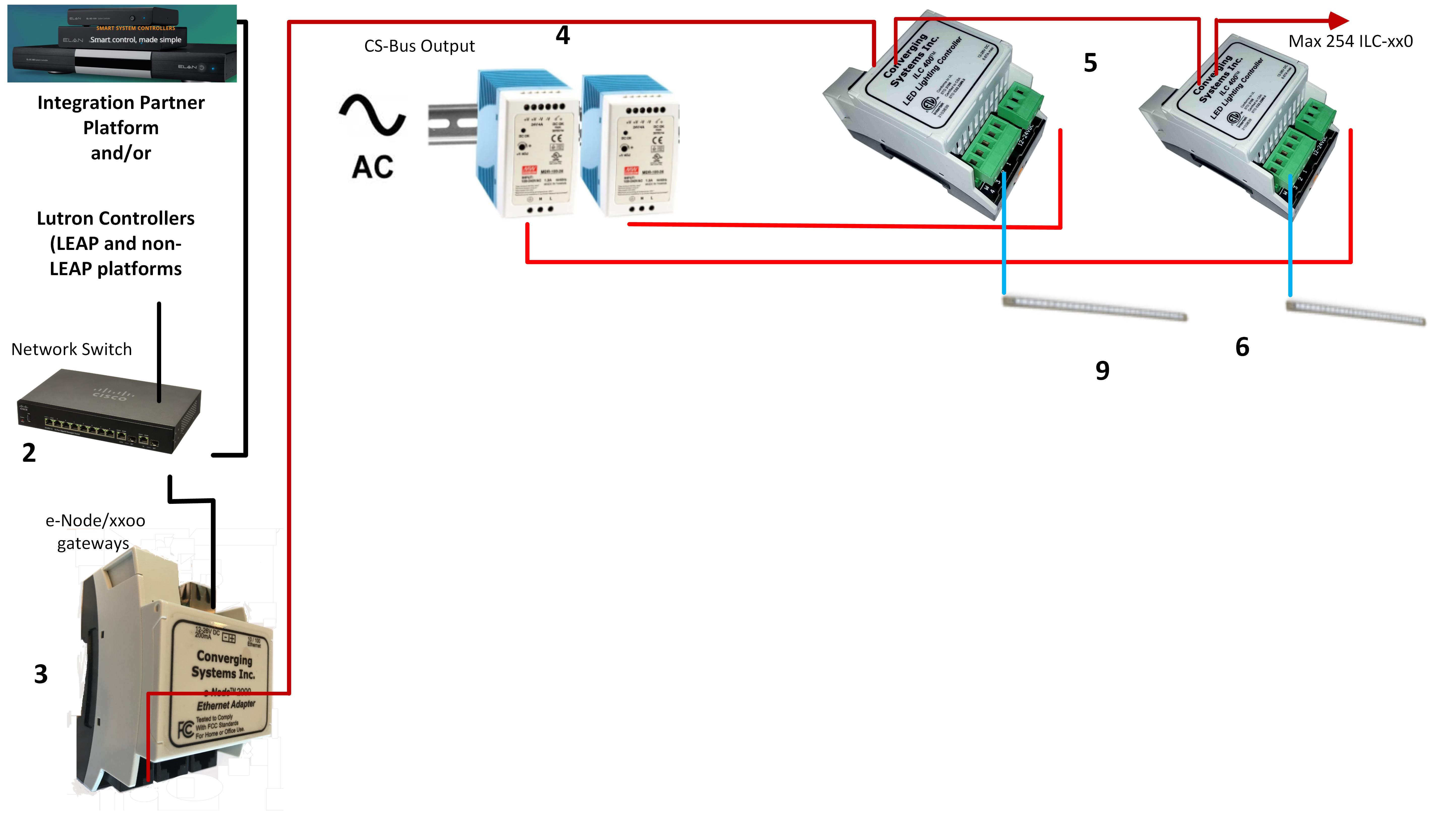
See figure below for basic overview of interconnections between components.

Mounting Considerations/Importance of Grounds
Selection of DIN rail enclosure/information regarding the placement of UL Class 2 approved Power supply Units (PSU).
- Selection of DIN-Rail Enclosures.
Please refer to this separate document for images showing Class 1 wiring run to power strips and then dealer-installed Class 2 installation of the ILC-xx0 and associated components.
- The importance of running Grounds to all ILC-xx0 controllers.
Verify that a known good earth ground is connected to each ground pin on the 3-pin green power connector to each ILC-xx0 device. Correct as necessary.
