Follow these steps to understand ZGN Addressing
Step 1a. Understanding Addressing.
All gateway products implement a sophisticated addressing scheme referred to as Z.G.N. (i.e., period delimited octets referring to Zone, Group, Node address) which allow any controller (IMC-xxx, ILC-xxx, DMX channel, or channel within CVM) to be (i) individual addressed, or (ii) addressed as part of almost an infinite number of subgroups or (iii) addressed to operate simultaneously system wide. Typically, no two controllers should share the same ZGN address. The following diagram shows to topology of this scheme.
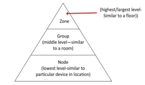
Typically all controllers from the factory have ZGN assigned as x.1.0 (where x=1 for motors and x=2 for LEDS). The “0” is assigned indicating that it is still an out-of-box (unprogrammed) product that NEEDs to be assigned to a non-zero number at minimum. For an LED controller, a typical address might be 2.1.1 for the first controller. The first field (# from 0~254 is the Zone address), the second field (# from 0~254) is the Group Address and the final field (# from 0~254) is the Node address. A Z/G/N of 2.1.1 would be entered as following

Step 1b. Examples of Assigning ZGN.
| Scenario | How Addressed | How Controlled |
|---|---|---|
| 2 devices to be controlled in unison |
|
2.1.0 |
| 3 devices to be controlled individually |
|
|
| 4 devices-2 be controlled as one bank and the other 2 to be controlled as another bank |
|
|